Overview
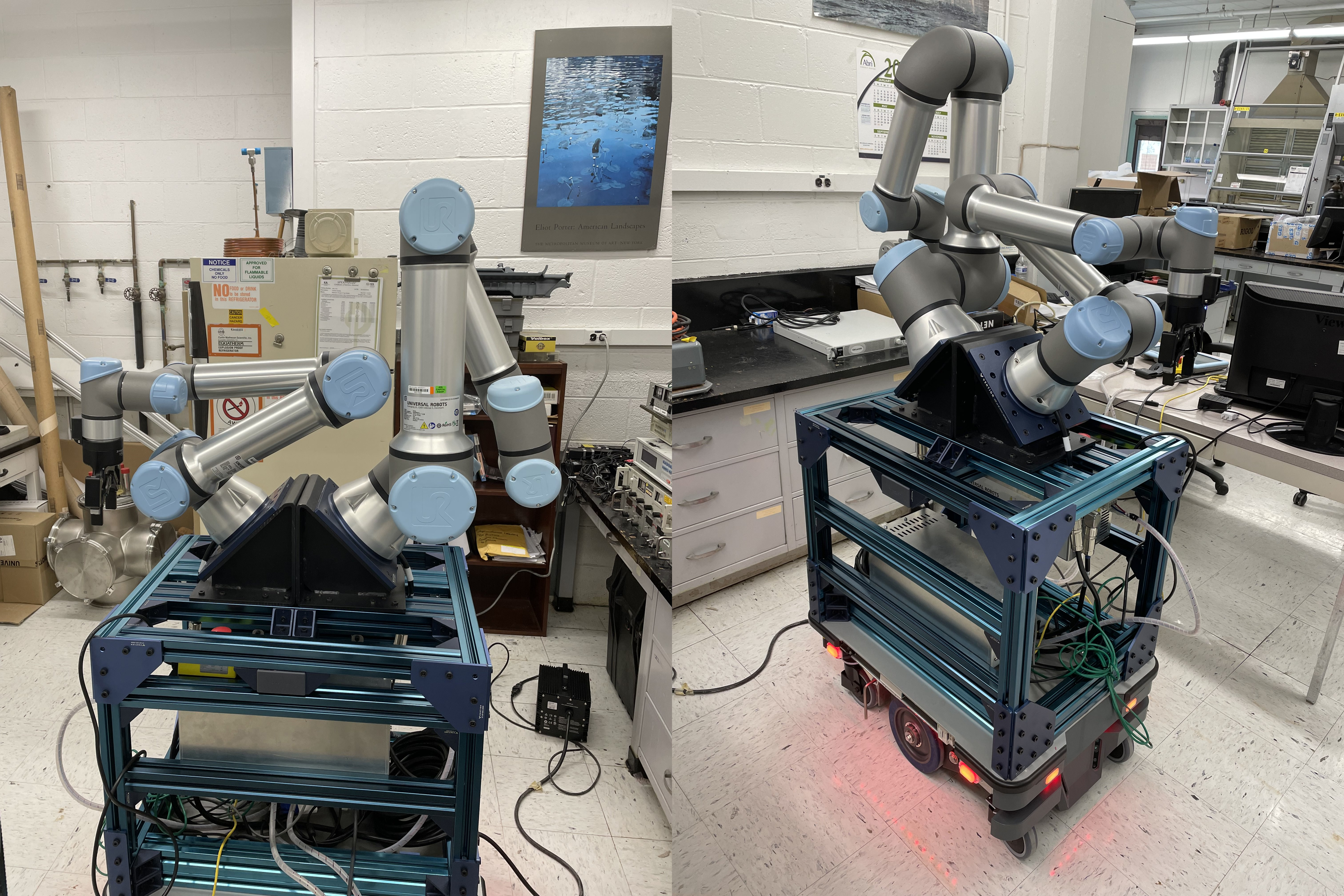
After gaining experience in a variety of areas in robotics, I wanted to work on a project in the areas I found the most interesting. This led me to work on a project with Argonne National Laboratory under the supervision of Dr. Jerry Nolen and Dr. Park. Dr. Nolen’s lab works with medical isotopes and retrieving them is a huge problem due to radiation levels and time constraints. The longer it takes for the sample to be taken, the more it deteriorates or decays. Currently, the way the sample is retrieved is through a human going into the radioactive area, with protective gear, and doing the steps required to get a hold of the isotope and take it out of the dangerous environment. A proposed solution is to make a robot go into the lab and get the isotope but the question was what system can help solve this problem. The system that was made was one composed of a UR16e, UR5e, and a MiR 250 mobile base.
The goal of this project is to use these three independent robots and have them work together to navigate through a radioactive environment, approach the isotope target, decouple it from the beamline and finally bring it back to researchers so that they can perform experiments and research on it.
To learn more about getting the system running, check out my Github Repo!
Skills Used:
- Robot Operating Software(ROS)
- MoveIt!
- C++
- Python
- Manipulation
- System Integration
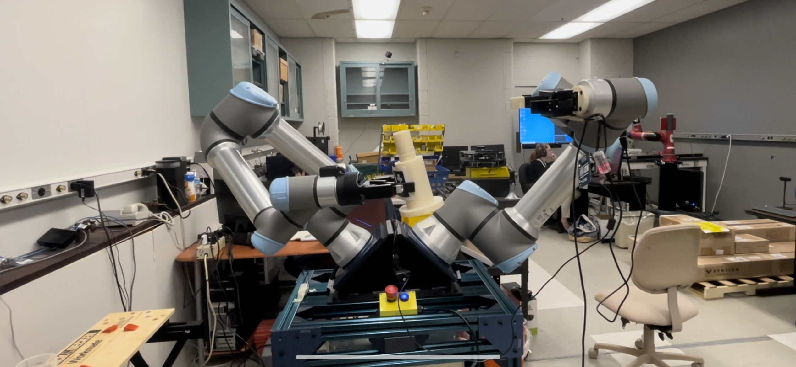
An initial test of the movement and manipulation capabilities of the system using only one goal and a relatively simple object to interact with.
Design of the System
The system was composed of two different arms due to budget constraints. One option was to use two UR5e to make the system symmetrical and balanced but this came at the cost of the total payload the arms could carry is 10 kg. This could limit the ability of the system to perform if faced with a heavy object. Although the system would be not symmetrical and it would require mounting the arms so that they are not imbalanced, the ability to have a total payload of 21 kg would allow the system to be versatile through a variety of different objects.
First Iteration
The initial system was composed of the core robotic components but with only one gripper attached to the UR5e and each arm was controlled by its own Raspberry PI4. The idea behind the two Raspberry PI 4s was to reduce the amount of load each computer would have to go through and each computer would run the driver for just one arm. A main computer would be used by the researchers and the three computers would share the same ROS_MASTER_URI so that the main computer can access the nodes/drivers for each arm without being connected to it directly. Besides having no gripper, the biggest flaw in this system was power. The two robotic arms and mobile base were being powered by the battery on the MiR base and with the battery being used by three robots already, adding two more sources of power consumption was going to be a problem if the power draw is too much for the onboard battery.
Second Iteration
The second iteration of the system now had two grippers! However, the new one was an old model Robotis Gripper that did not provide enough force to grip objects heavier than 3 kgs. However, it was enough for picking up light objects. In terms of the computer for the system, it was now down to just one Raspberry PI 4. This was influenced by the previously mentioned power issue but also because a MoveIt config package was made so that a single launch file could run both robot’s drivers and the MoveIt launch file can allow for both arms to move in the same ROS_MASTER. But an issue that came up was performance. Path planning was much slower when compared to just one computer per arm and this is to be expected since the computer was also running the full desktop version of Ubuntu so it had other processes occurring in the background. Increasing this performance with a single onboard computer that would not draw too much power led to the idea of using a Nvidia Jetson Nano but it still had many of the same shortcomings.
Third Iteration
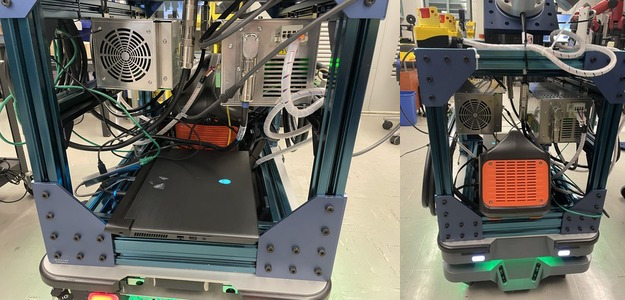
The final iteration of the system now had Robotiq grippers for each arm. The grippers were initially controlled through low-level control but eventually, the ROS drivers/wrappers for the Robotiq grippers were fixed and used. As for the computer of the system, a powerful Alienware laptop was used that was running Ubuntu and running both robotic arm drivers, the camera, and the manipulation node. A laptop is a great solution. It’s compact which is a huge benefit considering the amount of space on the system was limited and it’s powerful enough to enough everything without concern for performance. There was a small problem in the form of power. This computer drew much more power than its Raspberry Pi 4 competitor which had an average power consumption of 85 watts whereas the smaller computer only drew around 5-10 watts. The solution was to add an additional battery that could power the laptop for a full day of operation.
Manipulation
The main aspect of this project is manipulation. Working with single robotic arms is very common and so having two arms involves more things to account for setting up the system. The largest concern is collision among the arms. One way to alleviate the problem was to mount the arms at an angle so that the amount of overlap between the workspaces is decreased. There is another way that collision was accounted for and it will be addressed shortly.
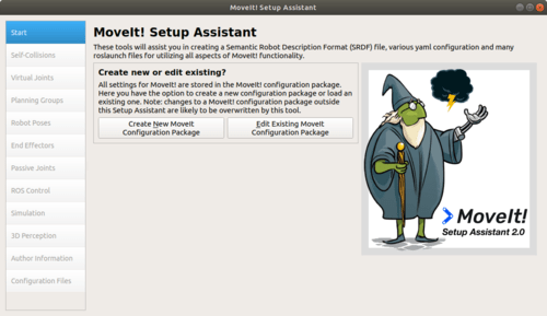
For this project, ROS was going to be the middleware that will allow for communication among the different systems. One of the benefits of ROS, is the motion planning plugin, MoveIt. MoveIt allows for motion planning of robotic arms and so a user can use the API to control the arm using cartesian movement, joint control, and so on. The only required once the package is installed to run the plugin on your robot is to create a MoveIt config package. This package allows you to motion plan for any robot but it requires the URDF for the robot. Once the dual arm URDF was made and uploaded, two different arms were defined in the config package and the collision is taken into account when motion planning on either arm.
The manipulation portion of the project took the most time to work on. This included many steps in the development. From the initial one-arm control, moving two arms in a single file, and finally having both arms work together to complete a task.
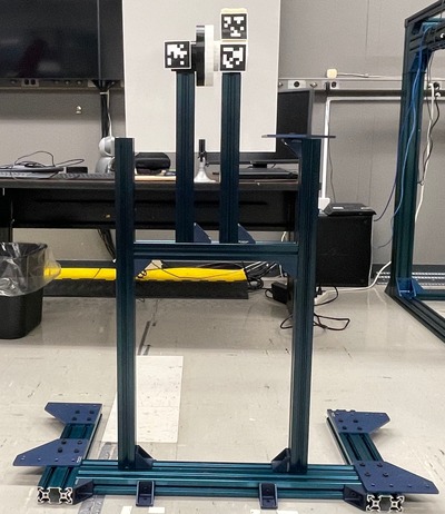
The main challenge of the project is that the arms have to be able to remove a water line from the target assembly and then remove the isotope from the assembly. This would then be transported to a researcher so research can be done on it. This process would involve three parts and to make the system more robust, AprilTags were used on each part to make detection and motion planning easier and more consistent.
For the first half of the final demo, the system detects the target assembly and it starts the process by identifying the water line, disconnecting it, and placing it to the side with the UR5e. Then the UR16e would remove the target from where is located to allow for the removal of the isotope. The UR5e would then identify the isotope and go to its position and remove it.
For the second half of the demo, the system would go about replacing the produced isotope with one that would be attached to the beamline. This starts with the system finding the replacement and then placing the old isotope next to the replacement. Then the UR16e moves to a position that would allow for assembly. The UR5e would then pick up the new part and then do motion planning to finish the assembly.
Navigation
The mobile base is a fundamental part of the project since it will be the catalyst for the system to move around. One of the biggest concerns for the project is that there are ROS drivers for the MiR robots, but there are no official drivers for the MiR 250 model. Even with efforts to get the drivers running, there are issues that make it not reliable.
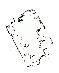
But it does come with onboard software that takes care of mapping, path planning, execution, safety, and many more features. The only problem with using the onboard software is communicating with the ROS system running on the computer. REST API came included with the MiR robot and this allows users to create Python scripts that can connect to the MiR software and perform actions such as sending a goal point and listening to the current status and other resources. Making a Python script that uses the API in a ROS node was straightforward and allowed communication from the ROS system to the MiR robot. Goal waypoints were defined on the map for the MiR 250 and these points can be called as the next goal when the system needs to get from location A to location B.
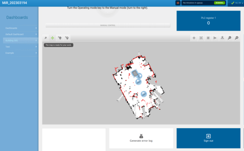
The onboard software performed very well when there weren’t close objects to the goal points. Problems would occur if the target goal was in a collision area, close to the red dots in the figure above. These issues were somewhat alleviated by going into the settings and adjusting the parameters for collision and reducing the threshold.
Integration
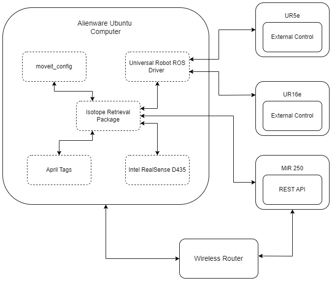
The system can be thought of as two states, navigation, and manipulation. The manipulation node calls upon services from the navigation node that allows it to send goals to the MiR base. This is done at the start of when everything is running and once the disassembling is completed. The manipulation node is the main node that is taking care of all the processes and calls the appropriate function when needed, whether is be decoupling the target isotope from the fixture to replacing the old isotope.
Conclusion
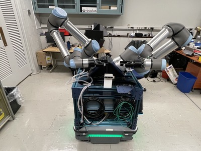
The system initially started as just hardware that can be individually controlled but now it is all integrated. The final system consists of an onboard computer, camera, arms that can path plan with the other arm in mind, and a mobile base that can communicate with the ROS system.
The system’s purpose was to be able to navigate a lab, interact with a part and bring it to another location to pass it on. The final system can successfully move from one part of the lab to another, do manipulation to remove the target from its holder, and then disassemble it. It then brings the isotope to the drop-off point and then picks up a replacement one and inserts it back into the target assembly. It proves the capabilities of the system and if more time was put into the project, it will be able to be deployed in the radioactive enviornment.
Overall the project was a success and the system is set up and ready for applications that would involve dual arm manipulation and navigation.
Future Work
There are a few areas that can be improved upon. The first one was briefly touched upon earlier, but object detection. The system can be improved by not requiring the use of AprilTags and instead using computer vision to detect the goal objects or another route is to only use one April Tag that can be used for each structure. Since each structure has fixed positions, you always know the position of the isotope relative to the AprilTag and so it would cut down on the number of markers needed.
The other major improvement is the ability to control both arms simultaneously. Currently, the system waits for one arm to complete a movement before the other one can move. Simultaneous movement can allow for the system to lift objects shaped in an odd manner to use both arms to lift up to the max payload it can support.
It would also be a good idea to add shielding to the system if it were to be deployed in a radioactive enviornment.